|
  A world-wide-web site
which comprehends A world-wide-web site
which comprehends
spirituality in a modern context in review of
ancient teachings
and religious belief-systems.
|
|
W e l c o m e T o S c
i e n c e L i n k s S i t e s)_9

Interaction Of The Universe To The
Individual
P R O M O T I N
G C O N S C I O U S N E S S O
N T H E I N T E R N E
T
|


SOLAR POWER |
Standard Solar
Power Modules and Arrays
|

Make This WebPage instantly
available in other languages
|


Become
Energy
Independent
We offer a range of complete solar power systems for homes connected to
the electric utility grid. Now almost any home can generate its own
electricity with a complete GE solar electric home power system. Engineered
to install quickly and reliably to provide years of automatic operation, our
residential solar electric systems include everything you need in one
complete package.
Features and Benefits
Available with or without an uninterruptible power
supply, our pre-packaged systems make solar electric home power more
convenient than ever. The residential system includes everything you need to
make your own electricity. Designed to provide years of automatic operation,
our systems come complete with solar modules, plug-and-play wiring, power
electronics, patented mounting kits for roof or ground mounting, a power
meter to monitor performance and complete documentation for contractors and
homeowners. GE solar systems are currently available only in the United
States. Please contact us at 800-310-7271or 201-755-6170for further
information. Also, please read our frequently asked questions for
residential systems and small commercial systems up to 10 KW.
For new
home builders, Aten Solar works with the builders and
contractors in order for the solar system to be easily integrated into
current building plans. The program provides builders with access to
experienced, knowledgeable professionals who can provide hands-on assistance
with training, permitting, installations, inspections and warranty support.
Builders who use Aten Solar have access to the only complete, pre-engineered
packaged solar power system on the market today. This fully integrated
system gives homebuyers a unique value added feature, a complete packaged
system designed and tested for system wide reliability and durability before
installation.
Pre-packaged Systems
- Solar
modules are
hail-resistant and produce 100 watts DC power in full
sunlight
- Solar
array
sizes
available from 12 to 96
modules
- Systems
generate
1,200 to 9,600 watts of solar
power in full
sunlight
- Pre-engineered rooftop mounting systems withstand up to 125 mph
wind (50
lbs/ft²)
- High
reliability
DC-AC inverter continuously
converts solar DC current into common household AC current
- Easily mounts above curved and flat tiles and asphalt
shingles
|
Make This WebPage instantly
available in other languages
|
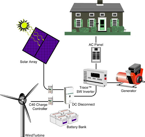
System
Diagram
Off
Grid System Components:
For a functional
description scroll down to read about the
individual System Components.
|
Off Grid System
Components |
Electric Panel: 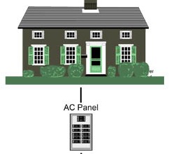
A distribution terminal for
electric wiring (also called a circuit breaker panel or breaker box). All the
wiring in a home or office terminates at a main electric panel and is supplied
with electricity from the inverter.
Engine Powered Generator:
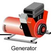
Uses an engine to generate
electricity, typically from natural gas, propane, or diesel fuel. Unlike
batteries, which store only a fixed amount of energy, a generator can produce
electricity for as long as it is supplied with fuel. A high-quality generator
can be fairly quiet, but never noise-free. Like all engines, generators require
periodic maintenance.
Battery Bank:

Stores energy for use on
demand. In an Off Grid electrical system the battery bank provides the reservoir
of energy available to power loads. The size of the battery bank determines how
long power will be available before battery recharging becomes necessary. The
power rating of the inverter determines how many appliances you can use at any
one time. The power rating of the battery charger determines how quickly your
battery bank can be recharged by a generator or other outside AC source.
There are a number of types of deep cycle batteries available which are
suitable for inverter operation. Some of them are sealed and require virtually
no maintenance.
Solar Electric Panels: 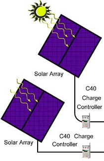
Convert sunlight
directly into electricity used to charge storage batteries. One of the most
reliable means to generate your own electricity, solar panels can generate power
for decades and require little maintenance. Solar electric generating systems
may be sized to provide ample power for most typical residential and commercial
power requirements.
Inverter/charger: 
Converts the DC power stored
in batteries to regular household current. Xantrex inverters, which consistently
provide better-than-utility power, make the use of solar power practical. Trace™
inverters have an efficiency rating as high as 96%, are noise-free, and function
as the brains of your fully automatic off grid electric system.
Most have
built-in battery chargers which are designed to be used with generators to
quickly recharge batteries when solar power is not sufficient.
Charge Controllers: 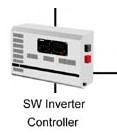
A charge controller is a
device used to control the amount of power generated from a PV array, wind
turbine, etc., to a battery. It is used to protect the batteries from harmful
overcharge conditions.
DC Disconnect: 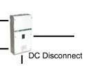
A DC disconnect is almost
identical to the AC circuit breaker found in your home. It is designed to
protect DC circuits (batteries, PV arrays, etc) from short circuits or overload
conditions.
Wind Turbine:
A wind turbine generates
electrical current as its blade spins. The faster the blade spins the more
electricity is generated. Residential scale wind turbines produce between 400
and 10,000 watts of power.
 I m p o r t a n t S
t u f f
I m p o r t a n t S
t u f f
EFFICIENCY
The best first step toward renewable energy is to make sure your
home is energy and water efficient. And, there are new federal tax credits to
help you!
INSTALLING A RENEWABLE ENERGY
SYSTEM
Finding a qualified contractor is an important first step. Here are other
steps in the process you should understand, so you can work intelligently with
your contractor:
Usually your contractor or installer will handle much of
the paperwork for you. But you will need to sign forms and manage some of the
steps yourself. We've outlined the main steps here for you.
LEARN ABOUT FINANCING YOUR
SYSTEM
Rebates, tax credits and other financial incentives are available today.
These can significantly reduce the price of installing a renewable energy
system. Also learn about property tax, leases, power purchase agreements and
more ...
GREEN TAGS
Are a versatile new way for consumers and businesses to participate in the
national transition to renewable energy. Green tags make it possible to support
renewable energy regardless of whether your state is deregulating its energy
markets. In some markets and situations Green Tags can be sold or traded. Check
with a Solar Pro to see what might be available to you.
|
Make This WebPage
instantly available in other
languages
|
|
Configurations
From One Appliance to an Entire Business
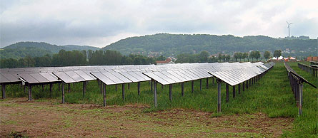
All solar electric systems
use solar cells, encapsulated in weatherproof modules, to convert free
sunlight into DC electricity instantly. How the modules are connected
and what happens to the electricity depends on the particular type of
application. Several typical system configurations are described
below.
|
Directly Connected
Systems
Solar Module(s) Connected Directly to a DC
Motor Load
Components: Solar modules and mounting
hardware, DC motor or pump and disconnect switch or circuit
breaker.
How it works: The solar module produces DC current that is used
immediately by a motor. As sunlight rises and falls, current and voltage
rise and fall, and the motor speeds up and slows down proportionally.
There is no power storage. The motor operates slowly during cloudy or
stormy weather and does not operate at
night.
Applications: Remote
water pumping, a ceiling or attic fan or a solar thermal (hot water)
circulation pump
Small Solar Module Connected to a Large
Battery
Components: Solar module, fuse and/or fused disconnect
switch
How it works: A small current flows from the solar module through a
starting battery to counteract any inherent self-discharge in the battery.
A trickle charge flows only during daylight hours, but on average offsets
any self-discharge.
Applications: Trickle charging of vehicle starting batteries (fleet vehicles,
seasonal road equipment like snowplows) and boat
batteries
Stand-Alone Systems
Solar Modules Connected Through a Charge
Regulator to Battery Storage
Components: Solar modules and mounting hardware, a charge
regulator, storage batteries and disconnect switches or circuit
breakers
How it works: A solar array produces DC current that passes through the
charge controller into storage batteries. The charge regulator reduces or
stops charging current to prevent battery overcharge. Small DC loads may be
connected to the charge regulator, which can then prevent battery
over-discharge. The battery operates loads at night and during overcast or
stormy days. Solar modules recharge the batteries when average or good
weather returns.
Applications: Remote
industrial areas (telecommunications, navigational aids, cathodic protection and
traffic systems) and remote home systems
Above System with DC-AC Inverter Connected
to Battery
Components: Above components with the addition of an
inverter and an AC distribution center
How it works: Same as above with the addition of an inverter to operate AC
loads. The inverter draws power from the battery and changes DC to AC
current and voltage. For safety, power is sent to the distribution center
which houses circuit breakers for individual AC circuits. The inverter
operates from battery energy day or night.
Applications: Remote
home systems
Above System with
Generator
Components: Above components with the addition of a fuel
generator (gasoline, diesel or propane), a rectifier and a sophisticated
hybrid system controller
How it works: The system controller monitors the battery voltage. When the
voltage drops to a safe but low level, the generator is turned on. AC output
is converted to DC power and recharges the battery. AC output can also be
used directly to power AC loads. When the battery reaches an almost full
recharge level, the generator is turned off. The solar array can be sized to
supply average GE needs throughout the year, and the generator is used to
fill in during seasonal low output periods and prolonged bad
weather.
Applications: Village power systems
Grid-Connected
Systems
Solar Modules Connected to a Utility
Interactive Type Inverter
and Utility Power Grid
Components: Solar modules and mounting hardware,
disconnect switches or circuit breakers and a grid interactive
inverter
How it works: The solar array produces DC current that passes through
inverter, which converts to AC current and voltage. Power is sent to the
utility meter and is either consumed immediately by home or business loads,
or is sent out to the general utility grid network. The utility meter spins
backwards, or two meters are used to record incoming and outgoing power. At
night, loads operate from utility power since the solar power system does
not produce power. The inverter shuts down automatically in case of utility
power failure for safety, and reconnects automatically when utility power
resumes.
Applications: Urban residential and commercial systems and utility-scale
power plants
Above System with a Bi-directional Inverter and Battery
Backup
Components: Above components with the addition of a
battery bank, charge regulator and bi-directional inverter.
How it works: The solar array charges the battery bank through a charge
regulator. DC power from the battery passes through the inverter and is
converted to AC current and voltage. Power is sent to the utility meter and
is either consumed immediately by home or business loads, or is sent out to
the general utility grid network. The utility meter spins backwards, or two
meters are used to record incoming and outgoing power. At night, loads
operate and the battery bank is kept trickle charged from utility power
since the solar power system does not produce power. In case of utility
power failure, the direct connection to the utility meter is shut down for
safety. Selected circuits in the home or business that are connected to a
special secondary inverter output continue to operate, drawing energy from
battery bank. The solar array recharges the battery each day until normal
utility power resumes.
Applications:
Urban residential and commercial
systems
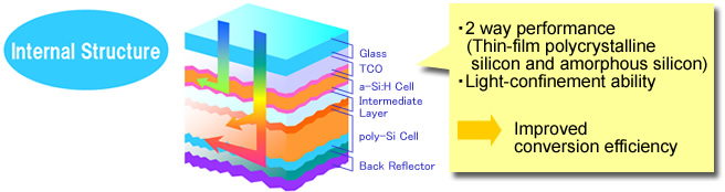
High Effective Hybrid PV

| |
Environmental
pollution and energy shortages are now of global concern. More interest is
focusing on photovoltaic (PV) power generation, which can use an unlimited
source of clean energy - the sun. Kaneka decided to begin research into
thin film silicon PV modules at an early stage. This has allowed the
company to assume a leading position in the industry over the past 20
years.
Kaneka's accumulated
expertise now makes it possible to offer next-generation energy all over
the world through its advanced PV systems that empower individuals to take
a proactive environmental role in their daily lives.
Crystalline-Si PV
modules lose some power-generating capability with rises in temperatures.
But Amorphous-Si PV modules have higher power generation capability during
extreme summer time. Amorphous-Si PV modules can deliver maximum
performance during summer afternoons. Therefore the amorphous-Si PV
systems can contribute during the time when the electricity is needed most
for air-conditioners in houses and offices.
*Kaneka Silicon PV's generated watt-power is
approximately same as that of other crystalline silicon PVs during the
winter months, but in summer the Kaneka Silicon PV generates significantly
more power compared to other crystalline silicon PVs.
Source:
"NEDO/Ritsumeikan University Demographic Module Field Test and Operational
Analysis" presented at the International PV SEC-11, Sapporo, Hokkaido,
Japan, 1999.
Installation location: Kusatsu, Shiga Prefecture Japan
Slope angle: 15.3 degree
|
|
*Kaneka Silicon PV's generated
watt-power is approximately same as that of other crystalline
silicon PVs during the winter months, but in summer the Kaneka
Silicon PV generates significantly more power compared to other
crystalline silicon PVs.
Source: "NEDO/Ritsumeikan University Module Field Test and
Operational Analysis" presented at the International PV SEC-11,
Sapporo, Hokkaido, Japan, 1999.
Installation location: Kusatsu, Shiga
Prefecture Japan Slope angle: 15.3
degree |
|
|

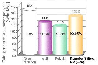
Kaneka's amorphous silicon (a-Si) has
superior light absorption per nominal watt power. Compared with
mono-crystalline (c-Si) or poly-crystalline (poly-Si), it generates
considerably more power per nominal watt power.
Assuming that the total solar radiation per
year (1.323kWh/m2) is 100%, Kaneka Silicon PV can produce 90.95% of
actually generated watt-power, much higher than that of other
crystalline |
silicon PVs (80 to 84%).
Source:
"NEDO/Ritsumeikan University Demographic Module Field Test and Operational
Analysis" presented at the International PV SEC-11, Sapporo, Hokkaido,
Japan, 1999. Installation location: Kusatsu, Shiga Prefecture Japan Slope
angle: 15.3 degree
*NEDO : New Energy and
Industrial Technology Development Organization
|
|

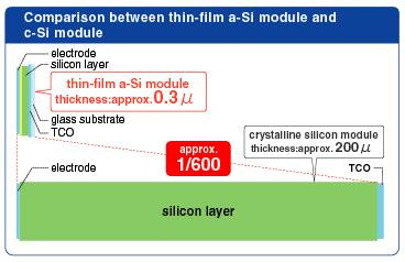
Another advantage is that the single junction
a-Si layer can be made extremely thin.
The thickness of a-Si cell
is 0.3, which is 1/600 of that of crystalline silicon
cell.
This uses less material and energy
thereby enabling high productivity for mass production (approx.
200).
|
|
|

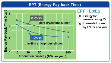
EPT is the time a PV module to "pay back" the
energy used in its manufacture by its own power generation.
The
EPT of amorphous-Si PV is 1.6 years, which is approximately 6 months
shorter than that of crystalline silicon PV (2.2 years).
EPT is one of the most important aspects when
evaluating the ecological benefit of PV
systems. |
Quality
·
IEC 61646 tested and certified
·
safety class II for 530 V system voltage (projected)
Guarantee
·
25 years power warranty (80%)*
·
12 years power warranty (90%)*
·
5 years product guarantee*
High
performance
·
power tolerance +10%… -5%
·
higher yield on plant due to higher power output on delivery
·
high yields even at high module temperatures
Ecological
advantage
·
Extremely low consumption on material -> energy payback time less than
2 years
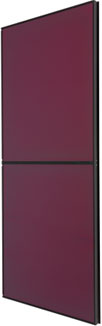
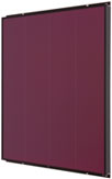
Design
·
Homogeneous colouring of frame and module surface -> high-class,
harmonic appearance
|
Electrical
Characteristics |
Stabilised
values |
Initial
values |
|
Nominal peak power (Wp) |
60,0 |
79,0 |
|
Guaranteed minimum power (Wp) |
57,0 |
75,05 |
|
Nominal voltage (V) |
67,0 |
74,0 |
|
Nominal current (A) |
0,90 |
1,04 |
|
Open-circuit voltage (V) |
92,0 |
96,0 |
|
Short-circuit current (A) |
1,19 |
1,22 |
|
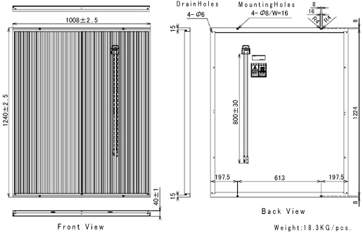
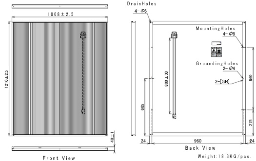
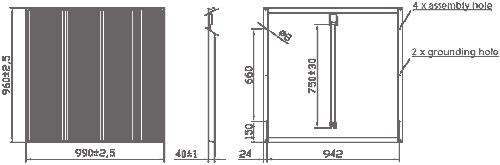
Physical
Characteristics |
|
Maximum system voltage (V) |
530 |
|
Length (mm) |
960 |
|
Width (mm) |
990 |
|
Height (mm) |
40 |
|
Weight (kg) |
14 |
|
Assembly holes ø 8 mm (pieces) |
4 |
Boxing dimensions:
1 crate = 44”W x 42” D x 44”H and
750 lbs.
There are 25 modules in a crate.
The crate is
separated into two compartments, one with 12 modules and one with 13
modules. Each module is separated from the others by a solid cardboard
separator sheet.
For price quotations on container shipments (1 x 20
FT container = 550 modules) or 1 x 40 FT container = 1100
modules)
Your
Price Qty 1 Total $9800.00 SKU 1.44KWKANTK
Product
Title 1.44KWTK
Kaneka Solar Prepackaged/Turnkey Grid Tie System
Image
Weight
(lbs) 915.00
Suggested
Products 1.8
KW GE Energy Brilliance Prepackaged/Turnkey Grid Tie
System
Your
Price Qty 1 Total $5625.00 SKU GSA-60
Product
Title 25
Kaneka Solar 60 Watt Modules Description:
60 Watt Amorphous
Silicon Solar Module-Sold as lot of 25
Image
Weight (lbs) 825.00
Your
Price Qty 1 Total $16889.00 SKU 3.0KWKANTK
Kaneka Solar Prepackaged/Turnkey Grid Tie System
Product
Title 3.0
KW Kaneka Solar Prepackaged/Turnkey Grid Tie System
Image
Weight
(lbs) 1725.00
Suggested
Products
1.44KWTK
Kaneka Solar Prepackaged/Turnkey Grid Tie System
1.8
KW GE Energy Brilliance Prepackaged/Turnkey Grid Tie System
25
Kaneka Solar 60 Watt Modules Description: 60 Watt Amorphous Silicon
Solar Module-Sold as lot of 25
|
|
Make This WebPage instantly available
in other languages
|
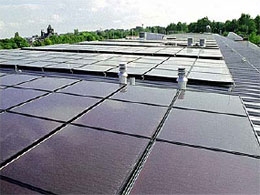
Pre-packaged
Systems
- Solar modules
are hail-resistant and produce 100 watts DC power
in full sunlight
- Solar array
sizes available from 12 to 96 modules
- Systems
generate 1,200 to 9,600
watts of solar power in
full sunlight
- Pre-engineered
rooftop mounting systems withstand up to 125 mph
wind (50 lbs/ft²)
- High
reliability DC-AC inverter continuously converts solar DC current into common household AC
current
- Easily
mounts above curved and flat tiles and asphalt
shingles
| |
|
|
|
|
|
|
|
|
|
|
|
| Grid Tie- 7.2 |
Grid Tie-7.4 |
Part |
Description |
|
|
|
|
|
|
|
|
| 36 |
37 |
GEPV-200M |
GE Energy 200 Watt Photovoltaic Module, Silver Frame, White
Back Sheet, 25 Year Warranty |
| 0 |
3 |
GE-2.5 Inverter |
GE
inverter-2500 watts, 240 Vac, 60Hz (Standard 10 Year Warranty) |
|
|
|
| 2 |
0 |
GE-3.0 Inverter |
GE inverter-3000
watts, 240 Vac, 60Hz (Standard 10 Year Warranty) |
|
|
|
| 0 |
0 |
GE-3.3 Inverter |
GE
inverter-3300 watts, 240 Vac, 60Hz (Standard 10 Year Warranty) |
|
|
|
| 0 |
0 |
GE-3.8 Inverter |
GE inverter-3800
watts, 240 Vac, 60Hz (Standard 10 Year Warranty) |
|
|
|
| 8 |
8 |
GE Mod5Rac |
Kit for 5 GEPV-200
Modules, 2 - 204" Rails, 8 Mid-clamps, 4 End clamps, 8 L-feet |
|
|
| 7 |
7 |
GE Splice-Clip |
Splice kit (2 splice bars and mid
clamps) |
|
|
|
|
|
| 1 |
1 |
GEPV-M2 |
GE Energy
Meter Duel Display (Production/Consumption) |
|
|
|
|
|
|
|
|
|
|
|
|
|
|
|
|
|
| $ 73,935.16 |
$ 78,535.39 |
Published
Price |
|
|
|
|
|
|
|
|
|
|
| $ 39,554.69 |
$ 41,820.09 |
Price Less Discount |
|
|
|
|
|
|
|
|
|
|
| |
|
|
|
|
|
|
|
|
|
|
|
|
| |
|
|
|
|
|
|
|
|
|
|
|
|
| Grid Tie- 9.8 |
Grid Tie- 10.0 |
Part |
Description |
|
|
|
|
|
|
|
|
| 49 |
50 |
GEPV-200M |
GE Energy 200 Watt Photovoltaic Module, Silver Frame, White
Back Sheet, 25 Year Warranty |
| 1 |
0 |
GE-2.5 Inverter |
GE
inverter-2500 watts, 240 Vac, 60Hz (Standard 10 Year Warranty) |
|
|
|
| 2 |
3 |
GE-3.0 Inverter |
GE inverter-3000
watts, 240 Vac, 60Hz (Standard 10 Year Warranty) |
|
|
|
| 0 |
0 |
GE-3.3 Inverter |
GE
inverter-3300 watts, 240 Vac, 60Hz (Standard 10 Year Warranty) |
|
|
|
| 0 |
0 |
GE-3.8 Inverter |
GE inverter-3800
watts, 240 Vac, 60Hz (Standard 10 Year Warranty) |
|
|
|
| 10 |
10 |
GE Mod5Rac |
Kit for 5 GEPV-200
Modules, 2 - 204" Rails, 8 Mid-clamps, 4 End clamps, 8 L-feet |
|
|
| 9 |
9 |
GE Splice-Clip |
Splice kit (2 splice bars and mid
clamps) |
|
|
|
|
|
| 1 |
1 |
GEPV-M2 |
GE Energy
Meter Duel Display (Production/Consumption) |
|
|
|
|
|
|
|
|
|
|
|
|
|
|
|
|
|
|
$ 100,589.47 |
$ 102,529.70 |
Published
Price |
|
|
|
|
|
|
|
|
|
|
| $ 52,808.70 |
$ 53,827.20 |
Price Less Discount |
|
|
|
|
|
|
|
|
|
|
|
|
| SKU |
1.44KWKANTK |
| Product
Title |
1.44KWTK Kaneka Solar Prepackaged/Turnkey Grid Tie
System |
| Weight
(lbs) |
915.00 |
| Your Price |
$9800.00 |
|
| |
|
|
| SKU |
GEB1.8 |
| Product
Title |
1.8 KW GE Energy Brilliance Prepackaged/Turnkey Grid Tie
System |
| Weight
(lbs) |
550.00 |
| Your Price |
$11490.00 |
|
| |
|
|
| SKU |
GEB2.6 |
| Product
Title |
2.6 KW GE Energy Brilliance Prepackaged/Turnkey Grid Tie
System |
| Weight
(lbs) |
667.00 |
| Your Price |
$15576.00 |
| Qty
1 | |
|
|
| SKU |
GEB3.0 |
| Product
Title |
3.0 KW GE Energy Brilliance Prepackaged/Turnkey Grid Tie
System |
| Weight
(lbs) |
745.00 |
| Your Price |
$17332.00 |
| Qty
1 | |
|
|
| SKU |
3.0KWKANTK Kaneka Solar Prepackaged/Turnkey Grid Tie
System |
| Product
Title |
3.0 KW Kaneka Solar Prepackaged/Turnkey Grid Tie
System |
| Weight
(lbs) |
1725.00 |
| Your Price |
$16889.00 |
| Qty
1 | |
|
|
| SKU |
GEB3.6 |
| Product
Title |
3.6 KW GE Energy Brilliance Prepackaged/Turnkey Grid Tie
System |
| Weight
(lbs) |
823.00 |
| Your Price |
$21050.00 |
| Qty
1 | |
|
|
| SKU |
GEB4.0 |
| Product
Title |
4.0 KW GE Energy Brilliance Prepackaged/Turnkey Grid Tie
System |
| Weight
(lbs) |
901.00 |
| Your Price |
$22538.74 |
| Qty
1 | |
|
|
| SKU |
GEB4.6 |
| Product
Title |
4.6 KW GE Energy Brilliance Prepackaged/Turnkey Grid Tie
System |
| Weight
(lbs) |
1019.00 |
| Your Price |
$27116.56 |
| | |
|
|
| SKU |
GEB4.8 |
| Product
Title |
4.8 KW GE Energy Brilliance Prepackaged/Turnkey Grid Tie
System |
| Weight
(lbs) |
1097.00 |
| Your Price |
$28064.99 |
| Qty
1 | |
Changing System
Parameters
If desired, the
system parameters may be changed from the default values.
| DC Rating (0.5 to
1000 kW) |
|
The size of the PV system is the nameplate DC power rating. This is
determined by summing the PV module powers listed on the nameplates on the
backsides of the PV modules in units of watts and then dividing by 1000 to
convert to kilowatts (kW). The PV module power ratings are for Standard
Test Conditions (STC) of 1000 W/m2 solar
irradiance and 25oC PV module temperature.
The default PV system size is 4 kW. This corresponds to a PV array area of
approximately 35 m2 (377 ft2).
Caution: To achieve proper results, the DC rating input must be the
nameplate DC power rating as described above, and not based on other
rating conditions, such as PVUSA Test Conditions (PTC). PTC are defined as
1000 W/m2 plane-of-array irradiance,
20oC ambient temperature, and 1 m/s wind
speed. PTC differs from standard test conditions (STC) in that its test
conditions of ambient temperature and wind speed will result in a PV
module temperature of about 50oC, instead
of the 25oC for STC. Consequently, for
crystalline silicon PV systems with a power degradation due to temperature
of -0.5% per degree C, the PV module PTC power rating is about 88% of the
PV module nameplate rating. If a user incorrectly uses a DC rating based
on PTC power ratings, the energy production calculated by PVWATTS will be
reduced by about 12% from the proper calculation. In essence, the effects
of temperature will have been erroneously compensated for twice, first
with the use of the PTC rating, and again as PVWATTS performs hour-by-hour
calculations of PV module temperatures and applies temperature corrections
from STC to the hourly PV energy values.
|
| DC to AC Derate
Factor |
| |
PVWATTS multiplies the nameplate DC power rating
by an overall DC to AC derate factor to determine the AC power rating at
STC. The overall DC to AC derate factor accounts for losses from the DC
nameplate power rating and is the mathematical product of the derate
factors for the components of the PV system. A list of the default
component derate factors used by PVWATTS and the ranges that might be
encountered in practice are listed in the table.
Derate Factors for AC Power Rating at
STC
| Component Derate
Factors |
PVWATTS
Default |
Range |
| PV module nameplate DC
rating |
0.95 |
0.80 - 1.05 |
| Inverter and Transformer |
0.92 |
0.88 - 0.96 |
| Mismatch |
0.98 |
0.97 - 0.995 |
| Diodes and connections |
0.995 |
0.99 - 0.997 |
| DC wiring |
0.98 |
0.97 - 0.99 |
| AC wiring |
0.99 |
0.98 - 0.993 |
| Soiling |
0.95 |
0.30 - 0.995 |
| System availabilty |
0.98 |
0.00 - 0.995 |
| Shading |
1.00 |
0.00 - 1.00 |
| Sun-tracking |
1.00 |
0.95 - 1.00 |
| Age |
1.00 |
0.70 - 1.00 |
|
| Overall DC-to-AC derate
factor |
0.77 |
|
The overall DC to AC derate factor is calculated by
multiplying the component derate factors.
For the PVWATTS default values:
Overall DC to AC derate factor
= 0.95 x 0.92 x 0.98 x 0.995 x 0.98 x 0.99 x 0.95 x
0.98 x 1.00 x 1.00 x 1.00
= 0.77
The value of 0.77 means that the AC power rating at STC is 77% of
the nameplate DC power rating. In most cases, the overall default value of
0.77 will provide a reasonable estimate for modeling the energy
production. However, if so warranted, users have two options to change the
overall DC to AC derate factor. The first option is to enter in the text
box a new overall DC to AC derate factor. The second option is to click
the Calculate Derate Factor button which provides the user
with the opportunity to change any of the component derate factors in the
table and then PVWATTS calculates a new overall DC to AC derate factor.
Descriptions of the component derate factors are described in the
following paragraphs.
The derate factor for the PV module nameplate DC rating accounts for
the accuracy of the manufacturer's nameplate rating. Field measurements of
a representative sample of PV modules may show that the PV module powers
are different than the nameplate rating or that they experienced
light-induced degradation upon exposure (even crystalline silicon PV
modules typically lose 2% of their initial power before power stabilizes
after the first few hours of exposure to sunlight). A derate factor of
0.95 represents that testing yielded power measurements at STC that were
5% less than the manufacturer's nameplate rating.
The derate factor for the inverter and transformer is their combined
efficiency in converting DC power to AC power. A list of inverter
efficiencies by manufacturer is at http://www.consumerenergycenter.org/cgi-bin/eligible_inverters.cgi.
These inverter efficiencies include transformer related losses when a
transformer is used or required by the manufacturer.
The derate factor for PV module mismatch accounts for manufacturing
tolerances that yield PV modules with slightly different current-voltage
characteristics. Consequently, when connected together electrically they
do not operate at their respective peak efficiencies. The default value of
0.98 represents a loss of 2% due to mismatch.
The derate factor for diodes and connections accounts for losses from
voltage drops across diodes used to block the reverse flow of current and
from resistive losses in electrical connections.
The derate factor for DC wiring accounts for resistive losses in the
wiring between modules and the wiring connecting the PV array to the
inverter.
The derate factor for AC wiring accounts for resistive losses in the
wiring between the inverter and the connection to the local utility
service.
The derate factor for soiling accounts for dirt, snow, or other foreign
matter on the front surface of the PV module that reduces the amount of
solar radiation reaching the solar cells of the PV module. Dirt
accumulation on the PV module surface is location and weather dependent,
with greater soiling losses (up to 25% for some California locations) for
high-trafffic, high-pollution areas with infrequent rain. For northern
locations in winter, snow will reduce the amount of energy produced, with
the severity of the reduction a function of the amount of snow received
and how long it remains on the PV modules. Snow remains the longest when
sub-freezing temperatures prevail, small PV array tilt angles prevent snow
from sliding off, the PV array is closely integrated into the roof, and
the roof or other structure in the vicinity facilitates snow drifting onto
the PV modules. For a roof-mounted PV system in Minnesota with a tilt
angle of 23o, snow was observed to reduce
the energy production during the winter by 70%; a nearby roof-mounted PV
system with a tilt angle of 40o experienced
a 40% reduction.
The derate factor for system availability accounts for times when the
system is off due to maintenance and inverter and utility outages. The
default value of 0.98 represents the system being off for 2% of the year.
The derate factor for shading accounts for situations when PV modules
are shaded by nearby buildings, objects, or other PV modules and array
structure. For the default value of 1.00, PVWATTS assumes the PV modules
are not shaded. Tools such as Solar Pathfinder may be used to determine a
derate factor for shading by buildings and objects. For PV arrays
consisting of multiple rows of PV modules and array structure, the shading
derate factor should be changed to account for losses occurring when one
row shades an adjacent row. The figure below shows the shading derate
factor as a function of the type of PV array (fixed or tracking); the
Ground Cover Ratio (GCR), defined as the ratio of the PV array area to the
total ground area; and the tilt angle for fixed PV arrays. As shown in the
figure, spacing the rows further apart (smaller GCR) corresponds to a
larger derate factor (smaller shading loss). For fixed PV arrays, if the
tilt angle is decreased the rows may be spaced closer together (larger
GCR) to achieve the same shading derate factor. For the same value of
shading derate factor, land area requirements are greatest for 2-axis
tracking, as indicated by its relatively low GCR values when compared with
those for fixed or 1-axis tracking. If you know the GCR value for your PV
array, the figure may be used to estimate the appropriate shading derate
factor. Industry practice is to optimize the use of space by configuring
the PV system for a GCR corresponding to a shading derate factor of 0.975
(2.5% loss).
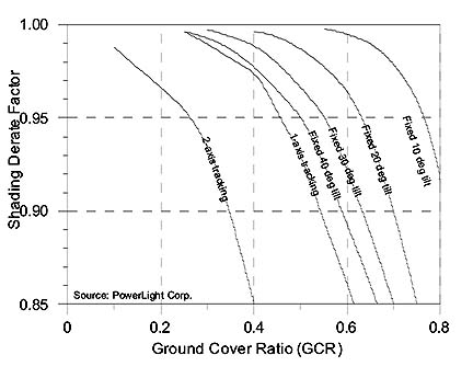
Shading Derate Factor for Multiple-Row PV Arrays
as a
Function of PV Array Type and Ground Cover Ratio
The derate factor for sun-tracking accounts for losses for one- and
two-axis tracking systems when the tracking mechanisms do not keep the PV
arrays at the optimum orientation with respect to the sun's position. For
the default value of 1.00, PVWATTS assumes that the PV arrays of tracking
systems are always positioned at their optimum orientation and performance
is not adversely affected.
The derate factor for age accounts for losses in performance over time
due primarily to weathering of the PV modules. The loss in performance is
typically 1% per year. For the default value of 1.00, PVWATTS assumes that
the PV system is in its 1st year of operation. For the 11th year of
operation, a derate factor of 0.90 would be appropriate.
Because the PVWATTS overall DC to AC derate factor is determined for
STC, a component derate factor for temperature is not part of its
determination. Power corrections for PV module operating temperature are
performed for each hour of the year as PVWATTS reads the meteorological
data for the location and computes the performance. A power correction of
-0.5% per oC for crystalline silicon PV
modules is used.
|
|
| Fixed or tracking
array |
|
The PV array may either be fixed,
sun-tracking with one axis of rotation, or sun-tracking with two axes of
rotation. The default value is a fixed PV array. |
|
|
|
| PV array tilt angle (0° to
90°) |
|
For a fixed PV array, the tilt angle is the angle from horizontal of
the inclination of the PV array (0° = horizontal, 90° = vertical). For a
sun-tracking PV array with one axis of rotation, the tilt angle is the
angle from horizontal of the inclination of the tracker axis. The tilt
angle is not applicable for sun-tracking PV arrays with two axes of
rotation.
The default value is a tilt angle equal to the station's latitude. This
normally maximizes annual energy production. Increasing the tilt angle
favors energy production in the winter, while decreasing the tilt angle
favors energy production in the summer.
For roof-mounted PV arrays, the table below gives tilt angles for
various roof pitches (ratio of vertical rise to horizontal run).
| Roof Pitch |
Tilt Angle (°) |
| 4/12 |
18.4 |
| 5/12 |
22.6 |
| 6/12 |
26.6 |
| 7/12 |
30.3 |
| 8/12 |
33.7 |
| 9/12 |
36.9 |
| 10/12 |
39.8 |
| 11/12 |
42.5 |
| 12/12 |
45.0 |
|
|
|
| PV array azimuth
angle (0° to 360°) |
|
For a fixed PV array, the azimuth angle is the angle clockwise from
true north of the direction that the PV array faces. For a sun-tracking PV
array with one axis of rotation, the azimuth angle is the angle clockwise
from true north of the direction of the axis of rotation. The azimuth
angle is not applicable for sun-tracking PV arrays with two axes of
rotation.
The default value is an azimuth angle of 180° (south-facing) for
locations in the northern hemisphere, and 0° (north-facing) for locations
in the southern hemisphere. This normally maximizes energy production. For
the northern hemisphere, increasing the azimuth angle favors afternoon
energy production, while decreasing the azimuth angle favors morning
energy production. The opposite is true for the southern hemisphere.
The table below provides azimuth angles for various headings.
| Heading |
Azimuth Angle (°) |
| N |
0 or 360 |
| NE |
45 |
| E |
90 |
| SE |
135 |
| S |
180 |
| SW |
225 |
| W |
270 |
| NW |
315 |
|
|
|
| Electricity cost |
| Version 1: For the U.S. and its Territories, the
default value is the average 2004 residential electric rate for the state
where the station is located. Source: Energy Information Administration.
For locations in regions outside the U.S., the default value is the
average 2004 or 2005 residential electric rate for the country where the
station is located. Sources: IEA Electricity Information 2005; IEA Energy
Prices & Taxes, 4th Quarter 2005; and Eurostat Gas and Electricity
Market Statistics 2005. For some countries, no electric cost information
is available and the default values are set to zero. For these countries,
the user should enter a value based on their knowledge. Electric costs are
presented in the country's currency. To convert results to another
currency, the user may go to http://www.oanda.com/converter/classic.
Version 2: Default value is the average 2004 residential electric rate
for the cell chosen by the user. Note that some areas are not covered by
any utility provider. For these areas the electric rate for the nearest
utlity service area is used. Source: Resource Data International.
|
|
Make This WebPage instantly
available in other languages
|
A high performance rechargeable
NiZn battery offers a viable alternative to hazardous NiCd
cells
 That is the headline of an article that claimed
that French and Spanish partners in EUREKA project NITIN SCOOTER made the
breakthrough that will finally make nickel zinc (NiZn) batteries economically
viable. Tests conducted in-house and by independent testing centers,
including the R&D Center of Electricite de France, demonstrate that their
NiZn batteries meet commercial requirements in terms of high cycle life, high
specific energy and power, and low cost. The partners in this EUREKA
project have overcome this problem and can now produce a safe alternative to
NiCd that can be used for over 1000 charging cycles.
That is the headline of an article that claimed
that French and Spanish partners in EUREKA project NITIN SCOOTER made the
breakthrough that will finally make nickel zinc (NiZn) batteries economically
viable. Tests conducted in-house and by independent testing centers,
including the R&D Center of Electricite de France, demonstrate that their
NiZn batteries meet commercial requirements in terms of high cycle life, high
specific energy and power, and low cost. The partners in this EUREKA
project have overcome this problem and can now produce a safe alternative to
NiCd that can be used for over 1000 charging cycles.
The battery was developed while researching a new rechargeable battery for
electric scooters. The resultant battery is environmentally friendly,
inexpensive and performs well, providing energy for large and small applications
requiring a rechargeable battery. The project partners have now created
successful prototypes and are looking for additional partners to take advantage
of the potentially huge market for the new batteries, either as the power supply
for a scooter or as a more general replacement for hazardous NiCd cells.
NITIN SCOOTER made use of a copper foam developed by S.C.P.S. in EUREKA
project E! 2179 3D STRUCTURES. By adding fine particles of a new conductive
ceramic from Spanish partner, SHS Ceramicas, the consortium succeeded in
stabilizing the electrode, preventing the damaging formation of zinc compounds
that caused loss of conductivity and short circuits.
According to the S.C.P.S. web
site, the answer to traditional zinc anode troubles has been found through
the definition of a new zinc electrode which combines three key-components
- a conductive collector network, constituted by a
specific "3D" structure (a copper foam), in which is pasted a plasticized
active mass
- particles of conductive ceramics, creating a secondary
conductive "micro" network in the active mass
- specific co-additives, linked with the ceramic
particles, in charge of increasing zincate retention in the anode
The direct cost of this battery is about 33% less than the NiCd battery
and gives a 40% greater power density. The batteries are available in
capacities up to about 100 Ah.
I hadn't heard of this battery
chemistry before, (shame on me), but it sounds like it has a place in the wold
of commercial, environmentally free battery
chemistry's.
|
Make This WebPage instantly
available in other languages
|

Information provided in this site is
deemed reliable but and should be independently verified.
PROMOTING CONSCIOUSNESS ON THE
INTERNET
 trujillo2001@yahoo.com
 WebMaster

Major redesign
and new functionality still under heavy development,
it's a huge undertake
to redesign a large
web-site and re-link and re-structure it, thanks for your patience.